Project Development
- Feb 26, 2025
- 12 min read
Hey guys! Welcome back to my blog! Hope you’ve all been doing well. Can’t believe it, but this is my last post for this module. Time flies, huh? So, I’ll try my best to make sure it’s a fun and engaging one for you guys to enjoy :D

In this blog, I’ll be documenting my experience developing a chemical device with my team. I’ll start with a brief description of our device and the inspiration behind it, before discussing how we planned, allocated tasks, and executed the project. I’ll then document the entire design and build process with videos, pictures, and screen captures to give you guys a clear view of our journey. I’ll also highlight my individual contributions, discuss the challenges we faced and how we overcame them. Additionally, I'll embed all of the Fusion 360 files used for our final prototype! Just a heads-up, we don’t have a Fusion 360 file for the final prototype itself since we didn’t 3D print its main body. Finally, I’ll wrap up with my personal reflection on the overall project development process.
Alright, without further ado, let's get started!
OUR CHEMICAL DEVICE

You might be wondering - what chemical device did my group decide to create? Well, we decided to design an automatic tea brewer! But why this project?

You see, tea brewing comes with many different challenges that we wanted to address. Students often have limited time in the morning to brew tea, but skipping it means missing out on a much-needed energy boost. Some try waking up earlier just to brew tea, but this results in less energy throughout the day due to lost sleep. Even for those who make the time, achieving the right brewing temperature and steeping duration can be tricky. Too hot, and the tea turns bitter. Too cold, and the flavours don’t fully develop.
So yeah, BIG PROBLEM :(

To address these issues, we worked on an automatic tea brewer that signals when the water reaches the optimal temperature and ensures the tea is steeped for the perfect duration. This saves time in the morning by eliminating the need to remake a cup due to brewing mistakes. With precise temperature and timing control, students can consistently enjoy a well-brewed cup of tea, providing the energy boost they need to start their day right.
Here is a hand sketch of our tea brewer!

In case you guys are slightly confused, here's how our tea brewer is supposed to work:
The temperature sensor measures the temperature of the water.
The Arduino board beeps once the water reaches the desired temperature.
The Arduino board beeps again once the tea has been steeped for the ideal amount of time.
The tea is dispensed through the tap while the fine mesh filter separates it from the used tea leaves.
There were still some tweaks made to our final prototype, which will be further elaborated later in this blog. For now, with the main concept of our device outlined, let's move forward and discuss the planning process we followed for this project!
TEAM PLANNING, ALLOCATION AND EXECUTION
Let's introduce my team first before we dive any deeper into our planning process!

Claudia, the CEO

Kylie, the CTO

Yutong, the COO

Jeriel, the CSO

and me, the CFO
Okay, now let's move on to the actual planning process!
Firstly, to effectively manage our $100 budget and ensure we had all necessary components, we developed a Bill of Materials (BOM). Here is my group's Bill of Materials!
Project Title: | Automatic Tea Brewer | ||||||
Team members: | Kylie, Claudia, Yutong, Ivan, Jeriel | ||||||
Created by: | Ivan, Claudia | ||||||
Date created: | 23/1/2024 | ||||||
BILL OF MATERIALS (BOM) | |||||||
No | Description of item | Supplier (include hyperlink to the item on website of seller) | Quantity Needed | Unit of Measurement | Unit Price (S$) | Total Cost (S$) | Available at W319 Lab? (Y/ N) |
1 | Temperature Sensor - Waterproof | 1 | piece | S$2.86 | S$2.86 | Y | |
2 | 5VDC HC-SR04 Ultrasonic Sensor | 1 | piece | S$1.18 | S$1.18 | Y | |
3 | Thermal plate | 1 | piece | S$5.47 | S$5.47 | N | |
4 | 3D printing filament | 1kg | kg | S$27 | S$27 | Y | |
5 | Basket type filter | 1 | piece | $9.95 | $9.95 | N | |
6 | Arduino UNO Board | 1 | piece | S$20 | S$20 | Y | |
7 | Cardboard | - | 1 | piece | S$6 | S$6 | Y |
Grand Total Cost: | S$72.46 |
Some of the key materials we needed included cardboard to build our main body, 3D printing filament to craft our casings and hinges, an Arduino board for programming, and a temperature sensor to measure the temperature of the tea.
Following the Bill of Materials, we developed a Gantt Chart to efficiently allocate tasks and ensure our project stayed on schedule.
Here is my group's Gantt Chart!

(please excuse my team members' names - wasn't my idea) You may notice have noticed that we really struggled to stay on track for this project. This led to a lot of problems in our prototype which will be elaborated on later in my blog. For now, with the BOM and Gantt Chart out of the way, we can now move on to the actual making of our prototype!
DESIGN AND BUILD PROCESS

Before I dive into this section, I just wanna say that I'm pretty bad at anything related to design. I tried my best though, so please bear with me if any drawing/sketch/component you're about to see looks kinda funny :D
Prior to building and assembling our prototype, we first had to prepare the components needed for it. This was split into three main activities:
3D Printing
Arduino Programming
Crafting of the Main Body
So, let's run through how we went about each of these activities before we dive into the actual building/assembling process.
3D Printing
3D Printing was mainly done by me and Claudia, so I can elaborate more for this part to talk about how I contributed to the construction of our prototype - basically this section will be way longer than the rest heehee.
Some of the components we had to 3D print included:
Casings for the Arduino Board and Breadboard

A hinge to be loaded with a spring

A sieve for the tea leaves

A tap to dispense the tea

And a lid with a latch, together with a button to open it!
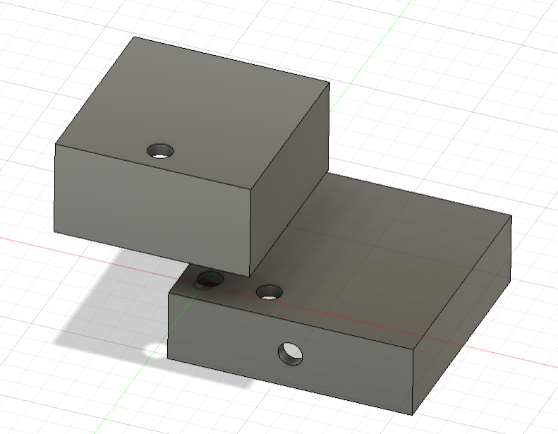
The photos above are actually screenshots from Fusion 360 when me and Claudia designed the components, but I'll embed the downloadable files later in this blog so you guys can play around with them :D

Some of the components were actually designed from scratch, such as the casings, the lid, and the hinge! I designed the casings, while Claudia designed the other two components. So, I'll just go over what it was like designing the casings.
The main thing I had to take note of while designing the casings was how tall they should be, as I had to take into account the height of the wires protruding from the boards when they were plugged in.
For the bottom casing with the breadboard, we sized the casing to be about 9cm x 6cm x 5cm as the actual board was about 8cm x 5cm x 3cm. For the top casing with the Arduino Board, we sized the casing to be about 7cm x 8.5cm x 5cm as the actual board was about 6cm x 7.5cm x 3cm. This was supposed to give us allowance for the wires to fit - but it kinda didn't work, which will elaborated later on ;D

There were some components that we had to find online though. For example, we weren't so sure how to design the sieve, so I just found one from this link (Customizable sieve / filter / strainer by DrLex - Thingiverse). The initial design was too big, so I had to scale down its diameter to about 5.8cm to ensure that the sieve would fit. For the tap, we actually had to reach out to a few friends who had designed valves/taps beforehand (shoutout gwen from 03 and hasnain from 06). So yeah, we got our files from them and adjusted them accordingly for our prototype. With the designing out of the way, we could then move on to 3D printing our components! Here are some photos of the 3D printer in action!

printing the hinge

halfway through printing the tap
Here are some more photos of the the 3D printed components themselves!

The Arduino casings


The hinge
The failed tap (i'll discuss more later on)
(i'm so sorry i cant find pictures of the sieve and the lid themselves, youll see them in the final prototype later on)
Alright, that's it for 3D printing, let's move on! (ion wanna touch fusion or a 3d printer ever agn)
Arduino Programming

Jeriel and Kylie were in charge of this, so I'll just try to convey whatever they said to me in this blog.
They had to programme the Arduino Board to do the following:
Measure the temperature of the water
Beep when the ideal temperature is reached
Beep again once the steeping time has been completed

I was told they kinda struggled with the code at first - something about defining the temperatures, there was always an error in the code saying that the values weren't defined even though they clearly were, like I saw it myself. Anyways, they sought help from a few friends (shoutout junkai from 03 and muhsin from 04) and were able to get the code to work in the end, which you'll see later in the demonstration of our final prototype.
I'll also be including the code later in this blog, but for now, here are some photos of the wiring before they were integrated into our prototype!

so

cute
Okay, that's it for Arduino Programming, let's move on to the last bit before we dive into the actual construction of our prototype! Crafting of the Main Body
Yutong was in charge of this, and honestly, I don't think many issues were encountered during this part of the process.
Our main body was to be made of cardboard, so this mainly involved cutting out a cylinder, making sure it's of the right diameter, and cutting out holes for the tap to dispense tea, and the temperature sensor to measure it.
Here's a photo of the main body!

Please ignore the lid and tap already attached - I couldn't find a photo of the main body itself. Also, the main body wasn't actually made of cardboard - we used a PVC pipe instead. I'll explain later HAHAHAHA
Andddd that's it for our main body!
After competing these activities, we could then move on to the actual building of our prototype!
First, we had to use a hot glue gun to glue some of our components together. This included gluing the Arduino Casings together, and the tap to the main body.

this is kylie glueing a piece of cardboard to the bottom of the arduino casing

and this is also kylie glueing the two casings together
Besides using a hot glue gun to assemble our components together, we also had to use sandpaper and a handheld drill to smooth out rough edges and ensure precision. This included getting rid of rough edges on our hinge and shortening it to ensure that it fits.

here's claudia using sandpaper to smoothen out our hinge

and here's yutong using the drill to shorten our hinge
After sorting our hinge out, we could finally finish our prototype by adding it together with the lid!
With that done, we finally had our prototype! Here are some photos of our prototype:

our

prototype
And here's a video of it in action!
For demonstration purposes, we've set our ideal brewing temperature to be 32 degrees Celsius instead of 80 degrees Celsius, and our ideal steeping time to be 5 seconds instead of 2 minutes. As you can see in the video, the Arduino board beeps once a reading of 32 degrees Celsius is obtained, and beeps again after 5 seconds, indicating that the tea has been steeped for ideal time, notifying our users that the tea can be dispensed! You may have noticed some unexpected changes in our prototype - ones I’ve been hinting at earlier when I said I’d explain later. For example, our body isn’t made of cardboard, and our hinge is completely different. So, let’s break down what happened.
PROBLEMS AND SOLUTIONS

Our group encountered three main problems throughout the building process, so let's go over them one by one.
Firstly, the height of our breadboard casing was too short, and the wires were hence unable to fit. Personally, I feel that this was my fault since when I estimated the height required, I didn't actually plug the wires in - I just added a few centimeters to the actual height of the breadboard, and it's clear that the allowance I gave wasn't sufficient, so my bad guys :(
Anyways, we didn't wanna remodel and reprint the casing. So, we decided to rectify this issue by cutting 6 strips of cardboard which we had leftover and used 3 strips on each side to elevate the casing such that the breadboard and wires could fit underneath it.

you can see the cardboard strips underneath the casings in this photo :)
After adding the cardboard strips, the wires could fit. So yay, problem 1 solved!
Secondly, our cardboard body was too weak to handle the tension of the hinge when we first tested it out. So, we ended up replacing the entire cardboard body with a PVC pipe instead and cut holes accordingly to fit the probe and tap.

Now, did this allow for our hinge to work? Um, not really - let's just move on to the next problem heehee
So yeah, lastly, our spring-loaded hinge just didn't work no matter how many reprints or adjustments we made. So, we kinda gave up on it and replaced it with a metal strip that sprung back - I don't really know how to explain this so here's a video.
So basically, the metal strip returns the lid back to its position, while the spring holds it down. This ended up working out well, so yay - problem 3 solved!
Oh also, there was one problem that we were unable to solve, and that was the tap :(
We reprinted the tap multiple times but were unable to get it to work, as its design needed supports that were really hard to remove afterwards. We weren't so sure how to remove them without breaking the actual tap. So, we just used a broken tap for our prototype, which doesn't actually turn. We would've loved to find a solution to this problem, but we really couldn't, so :(
So yeah, those are the problems we encountered throughout the process of building our prototype. I think it's clear that my group and I aren't the best at designing and building things, but we tried our best :D
Alright, with the problems and solutions out of the way, I'm almost done with this blog! Let's move onto the next part :)
PROJECT DESIGN FILES
As I've mentioned earlier, I'll be including all the Fusion 360 files, as well as the code, in this blog. Sooo, that's what this section is for.
Let's start with the Fusion 360 Files!
(oh yeah, to download them, just click Open in Fusion)
Here are the Arduino casings
Here is the hinge (which we ended up not using, but we intended to use the smaller one)
Here's the sieve
Here's the tap
and here's the lid and latch (which we also didn't end up using)
(as mentioned earlier, we don't have a Fusion 360 file for our final prototype since our main body was constructed with a PVC pipe instead)
Alright, with the Fusion 360 Files out of the way, let's move on to our code.
Here's the code we used!
Okay, onto the last part of this blog!
PERSONAL LEARNING REFLECTION
This is gonna be my last personal reflection for these blogs, ever (I hope). So, I'll try to make it a good one :)
Throughout this project, I had the opportunity to apply skills I learned last semester in ICPD, such as 3D modeling and printing, alongside new skills acquired this semester in CPDD, including Arduino programming and project planning. Bringing these elements together to develop our final prototype was both challenging and rewarding.

One major takeaway from this project is the importance of collaboration and having connections. I’m really grateful for the help we received from friends who assisted with the code and the 3D modeling of the valve, as well as Ms. Tan, who guided us along the way. Without their support, we would have struggled even more to complete our prototype. This highlighted the value of seeking help when needed and working as a team to overcome obstacles.
That being said, I couldn't help but notice that other groups' prototypes were SO MUCH BETTER. Like the prototypes from other classes makes ours look STUPID. I believe our struggles stemmed from both a lack of proficiency in design and our inability to adhere to our Gantt chart schedule. The delays in our process led to rushed decisions and limited time for refinements, which ultimately affected the quality of our final product.

On a personal level, I recognise that I could have contributed more to the hands-on aspects of the project. You may have noticed that I'm not actually in any photos of the building process. It's honeslty because I lack confidence in hands-on activities. I've got like really shaky hands - if you remember the shark making thing we did in ICPD, I couldn't use the penknife properly. The designing of this prototype definitely gave me the opportunity to improve on my hands-on skills, but I honestly didn't seize it. Moving forward, I'll try to contribute more in this aspect by telling myself 'I won't survive if I dont know how to use basic tools". On the other hand, while I did improve my 3D modeling skills, I still feel that I have a long way to go before I’m truly proficient. More importantly, this project has taught me valuable lessons about working effectively within a team, managing time constraints, and adapting to unforeseen challenges.
As for whether I’ll use these skills in the future - truthfully, I don’t see myself pursuing anything product design-related. However, if I ever find myself working on a project that requires 3D modeling, programming, or structured planning, I know that these skills will come in handy. Regardless, the experience of problem-solving, teamwork, and overcoming setbacks will be useful in any field I pursue.
ALRIGHT. That's it for my final blog, and I really hope it's my final one. Jokes aside, I hope it’s been an interesting read for you guys. Thanks for following along on this journey, and I appreciate all the support! GOODBYEEEEEEE :DDDD


Comments